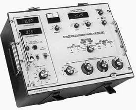
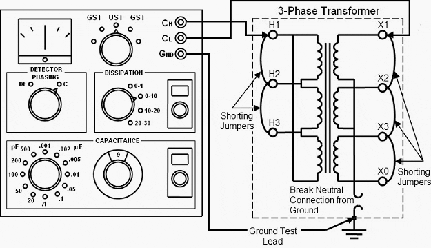
Capacitance and Dissipation Factor Test
The voltage level is selected to meet the requirements in applicable equipment standards. M2 Thermal Guard III constructed with 58X optimized heat dissipation surface and double-sided M2 heatsinks to prevent throttling and bottlenecks on high-speed large capacity of PCIe 40 M2 SSDs.

Power Transformer Capacitance And Dissipation Factor Test
This capacitance value is the Coss measured at Vds 80 Vdss.

. Charge device with 15X rated voltage in test chamber set at 85ºC 2ºC for 1000 hours 48 -0. Meanwhile the literature suggests that cable manufacturers have used power factor insulation tests in the laboratory since the very early 1900s. Remove from test chamber and stabilize at room temperature for 24 2 hours Capacitance Variation 125 Dissipation Factor.
Now lets look at the dielectric strength. Sinusoidal waveforms have an RMS value of 0707 the reciprocal of the square root of 2 and a form factor of 111 07070. After following life test with DC voltage and 105 2 ripple current value applied DC leakage current Within the initial limit Rated voltageV Dissipation factortan δ For capacitance value 1000 μF add 002 per every 1000 μF.
A non-solid electrolyte covers the rough surface of the oxide layer serving in principle as the second electrode - of. The form factor of an AC waveform is the ratio of its RMS value divided by its average value. This increases the sensitivity of the test and helps you to better assess the insulation.
Also material used for high capacitance requires high dielectric constant and low dissipation factor. On the other hand some polymers can have the relative permittivity of up to 100000. Measure parameter capacitance dissipation factor insulation resistance AVX ENHANCED SOFT TERMINATION BEND TEST PROCEDURE Bend Test The capacitor is soldered to the printed circuit board as shown and is bent up to 10mm at 1mm per second.
Linear derating factor 029 WC Single pulse avalanche energy b EAS 75 mJ Repetitive avalanche current a IAR 56 A Repetitive avalanche energy a EAR 43 mJ Maximum power dissipation TC 25 C PD 43 W Peak diode recovery dVdt c dVdt 55 Vns Operating junction and storage temperature range TJ Tstg-55 to 175 C. Aluminium capacitors are polarized electrolytic capacitors whose anode electrode is made of a pure aluminum foil with an etched surface. Dissipation Factor tanδ at 1 kHz Maximum Values at 25C 5C 03 02 at 1 kHz 25C 5C Test Voltage Between Terminals The 100 screening factory test is carried out at 5000 VDC2500 VAC.
OMICRON serves the electrical power industry with innovative products and services for testing diagnostics and monitoring of assets worldwide. In physics the dissipation factor DF is a measure of loss-rate of energy of a mode of oscillation mechanical electrical or electromechanical in a dissipative systemIt is the reciprocal of quality factor which represents the quality or durability of oscillation. Contact factory for optional specification part numbers that are tested at 15X rated voltage.
The test can be conducted at different frequencies often between the 10Hz and 2MHz range. Units RθJC Junction-to-Case 045. Its unique features allow better assessment of the insulation system.
Figure 3 shows the standard Coss test circuit. Linear Derating Factor 10 WC Single Pulse Avalanche Energy b EAS 580 mJ Repetitive Avalanche Current a IAR 18 A Repetitive Avalanche Energy a EAR 13 mJ Maximum Power Dissipation TC 25 C PD 125 W Peak Diode Recovery dVdt c dVdt 50 Vns Operating Junction and Storage Temperature Range TJ Tstg-55 to 150 C. Tests are made by measuring the capacitance and dissipation factor power factor of a specimen.
Consider an air capacitor with the distance between the electrodes being 01mm. The CP TD12 and CP TD15 include a high-voltage source reference capacitor and measurement electronics. Non-Destructive Full Sheet Resonance Test for Permittivity of Clad Laminates 0589.
Using such materials it is possible to achieve the same capacitance in a much smaller volume opening possibility for miniaturization. The board is placed on 2 supports 90mm apart capacitor side down. Electrical potential energy is dissipated in all dielectric materials usually in the form of heat.
The values measured will change when. Dissipation Factor of Flexible Printed Wiring. C 25C Power Dissipation W P D T C 100C Power Dissipation Linear Derating Factor WC T J Operating Junction and C T STG Storage Temperature Range Soldering Temperature for 10 seconds Mounting Torque 6-32 or M3 Screw N Thermal Resistance Parameter Typ.
The result is based on internal lab test for reference only real performance may vary. Tan delta power factor testing at 12 kV and 500 mA for successful testing of high capacitance objects without the use of an external inductor. With the TDX120 add-on the TRAX becomes are the most advanced tan delta power factor testing instrument on the market.
Square-shaped waveforms always have crest and form factors equal to 1 since the peak is the same as the RMS and average values. Test Circuit For Coss CB is Capacitance Bridge Coss DUT Cm Ck Ck - Cm Each time the MOSFET turns on the energy stored in the output capacitance will be dissipated in the device with Coss at the Vds voltage prior to. If a CMOS gate is operated in a static unchanging condition it dissipates zero power ideally.
The TRAX coupled with a TDX also provides PFDF test capabilities. There is a caveat to this advantage though. The sample must be flat and larger than the 50mm.
Low Frequency Dielectric Constant and Loss Tangent Polymer Films 0795. The CP TD12 and CP TD15 are accessories for TESTRANO 600 CPC 100 or CPC 80 for performing powerdissipation factor and capacitance measurements. The ratio of the power dissipated in the test material to the power applied is dissipation factor.
Power Factor Test Sets provide a comprehensive AC insulation diagnostic test for high voltage apparatus such as transformers bushings circuit breakers cables lightning arrestors and rotating machinery. While the power dissipation of a TTL gate remains rather constant regardless of its operating states a CMOS gate dissipates more power as the frequency of its input signals rises. Dielectric Constant and Dissipation Factor of Printed Wiring Board Material--Micrometer Method 1085.
September 2014 DocID026535 Rev 1 135 AN4544 Application note IGBT datasheet tutorial Introduction This application note is intended to provide detailed explanations about parameters and. The sum of DC and ripple peak voltage shall not exceed the rated working voltagewhen the. The aluminum forms a very thin insulating layer of aluminium oxide by anodization that acts as the dielectric of the capacitor.
Stable capacitance under high temperature. The Delta 4XXX series is Meggers dedicated power factor dissipation factor PFDF and capacitance test instrument for field use.

Power Transformer Capacitance And Dissipation Factor Test

Capacitance And Dissipation Factor Tan Delta Test Of Transformer Youtube

Tdx 5000 Tan Delta Diagnostic System Delta System Energy System
0 Response to "Capacitance and Dissipation Factor Test"
Post a Comment